• Proper care of compressed gas cylinder valves includes (but is not limited to) the this.
  • Master valves are essential equipment when considering the installation of an irrigation system.
  • Balloon fillers are the ultimate product, they ease the job while filling a large quantity of balloons within a few minutes.
  • Chlorine valves are exposed to various risks referring to the chemical properties of the liquid
  • Rego valves and regulators were the first to be designed especially for propane gas.

Sunday 18 November 2018

A Brief about Pressure Relief Valves

What is Pressure Relief Valves?

A Pressure Relief Valve (PRV) or relief valve is a type of safety valve that is used to control the pressure in a system that might otherwise disturb the process and consequently lead to system failures. It is designed to open at a pre-determined pressure level to protect other equipment from being damaged due to excess pressure. It aims at protecting property, life and environment.

Image Source - Wikipedia

What is the function of Pressure Relief Valves?

Normally, the pressure relief valve remains closed until pressure raises to the desired set pressure. When this level crosses, the valve opens and continues to further open and diverts the excess gas/ liquid to pass away. The valve closes again when the upstream pressure falls below the set pressure.

What are the Importance of Pressure Relief Valves?

Heavy gas equipment or industrial machineries that require gases at a certain set pressure level for proper mechanism can sometimes misbehave and if proper safety precautions are not observed may cause heavy loss to life and property. The most common causes of over-pressure are blocked discharge, thermal expansion, chemical reaction, cooling system failure, heat exchanger tube rupture, etc. These indents can happen suddenly at a much unexpected hour and may also take place simultaneously. Therefore installing the correct pressure relief valve is of utmost necessity. It is your responsibility to determine a scenario for the appropriate selection of the relief valve.

Schematic diagram of a conventional spring-loaded pressure relief valve. Image source - Wikipedia

How to Select the Correct Pressure Relief Valve?

Mainly, there are two types of safety valves – Pilot operated safety valves & Spring loaded safety valves.

Pilot Operated Safety Valve
The pilot valve actuates at the set pressure and prevents medium from being routed to the vented dome. Due to the vents in the dome, closing force does not become a condition for system overpressure to push the main valve open and results in the opening of the main valve. The opening is either gradual and partial or rapid and complete. In case of drop in the system pressure, the pilot valve actuates and re-routs the medium to the dome, repeating its procedure.

Spring Loaded Pressure Relief Valve
In this types of valves, an increase in pressure results in increase in the spring force. The system pressure must raise enough to lift the valve. For this reason, most pressure relief valves are equipped with a secondary control chamber to enhance the lift by allowing fluid to enter the chamber that exposes a larger area of the disc to system pressure.

This causes an incremental force change that causes the valve to open at a rapid rate. Simultaneously, the direction of the fluid flow is reversed and the momentum thus created further enhances the lift. Due to this setting, the valve remains open until the pressure reduces to a level below the set pressure.

Tuesday 13 November 2018

CO2 Regulators & Cylinders for Aquariums

8 Tips to Remember Before Using CO2 Regulators & Cylinders for Aquariums


CO2 cylinders and regulators are primary components of kegerators, aquariums and are commonly used in many applications. However, when working with CO2 cylinders and regulators, here are some tips you must know to be safe during the operation.

  1. When it is time to refill, do not simply remove the CO2 regulator. Relieve all the working pressure from the low pressure gauge to prevent further damage to the gauge during re-installation of the regulator.
  2. After re-filling your CO2 cylinder, vent it for 1 or 2 seconds before installing any components to the cylinder. This helps remove any debris that may have wedged in the cylinder valve. Preventing debris from entering also prolongs the life of your CO2 equipment.
  3. Make sure the cylinder reaches room temperature before re-installing the Co2 regulator. This ensures equalization of the pressure in the cylinder and enables it to take accurate pressure readings.
  4. Put your seal between the regulator and the cylinder valve. Remember to hand-tighten the seal if you are using a permaseal as a wrench is usually not required.
  5. When all is done and you are installing the regulator, ensure a tight connection using a crescent wrench or CO2 wrench so that there is no loss of CO2.
  6. Remember not to over-tighten the bubble counter on your CO2 regulator as this may cause the bubble counter to break off or damage the components that prevent contamination of your regulator.
  7. Always use a check valve in the CO2 tubing to protect your CO2 equipment as it prevents water from spilling out of the aquarium through the tubing towards the regulator.
  8. If you face a problem with your CO2 regulator, do not attempt to diagnose or repair on your own without prior consultation of our experts.

Evergreen Midwest Co. has trained professionals and industry experts to give you proper advice for all your regulators and valves. You can contact us at 800.659.3358. We also have a wide selection of industrial regulators, valves and valve accessories that are tested for performance as per the latest international standards.

Friday 28 September 2018

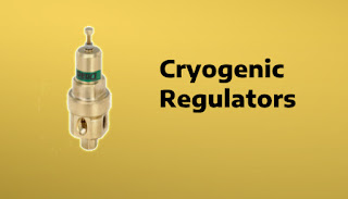
Cryogenic Regulators - Understanding Cryogenics and Associated Hazards


Cryogenic liquids are formed when gasses are converted into liquid form. They are liquefied gases that have a boiling point of -150°C (-238°F). As there is a substantial difference between the gas and surrounding environment, it requires a special equipment to contain these liquids. Typically, the arrangement consists of a pressure control system, a storage tank, piping required for fill, supply, one or more vaporizers, and vaporization.


Characteristics of Cryogenic Containers

The tank looks like a vacuum bottle that is manufactured to keep heat away from the liquid. The cryogenic liquid cylinders are vacuum jacketed pressure vessels that are insulated too for obvious reasons. Vaporization of the liquids is a continuous process due to heat leak of the containers. However, the rates of vaporization depend upon the volume of the stored product or design of the container. The containers holding these liquids are manufactured in accordance to the latest industry standards and comply with all the industrial cylinder regulations. They are fitted with insulated rigid or flexible lines that are used to remove the liquid from the containers and hence minimize the loss of the liquid product to gas. The cylinders are designed to dispense gases like Argon with standard CGA (Compressed Gas Association) outlets along with suitable cryogenic regulators. The cylinders have capacities between 80 and 450 liters of liquid and operate at pressures up to 350 psig.


Handling & Storage of Cryogenic Containers

The cylinders must be stored in a confined space where adequate ventilation is available. They should also be equipped with cryogenic regulators that control internal pressure build-up. Users must take care not to tamper with, remove, or plug any pressure relief device without proper monitoring. No unprotected body part must be exposed to un-insulated pipes or equipment containing these critical-natured products as the extremely cold metal causes the flesh to stick fast and tear when attempting to withdraw from it. Instead, experts suggest using a hand truck for moving these containers. The containers should always be held and stored in an upright position and must not be dropped or rolled on their sides. 
DO NOT USE ADAPTERS – as mentioned in the container’s caution instructions. Always use proper connection. Industry professionals suggest using a check valve or some protective apparatus on gas withdrawal systems to prevent reverse flow of the liquid. The piping must always be equipped with pressure relief devices to prevent the cryogenic liquids or cold gases from getting trapped in piping between valves.

Evergreen Midwest has been serving the industry with its industry-compliant valves and regulators since 1978 and adheres to the highest quality standards while delivering products to customers. For any of your industrial equipment requirements, especially gas regulators and valves, please feel free to contact us by phone at 1800.659.3358 or visit our website at https://www.evergreenmidwest.com/ to get an insight of all the products we provide.

Source - https://www.evergreenmidwest.com/blog/2017/07/03/understanding-cryogenics-and-the-associated-hazards/


Wednesday 26 September 2018

Chlorine Valves - What Risks are Chlorine Valves Exposed to?

Chlorine valves are exposed to various risks referring to the chemical properties of the liquid: 

Hydroscopic: In case the water content in dry chlorine is more than 50 parts per million, ferric chlorides (CL3F3) and hydrochloric acid (HCL) are formed. The HCL is highly corrosive and has the potential to damage the piping system that are made from carbon steel while the CL3F3 can create problems for seating surfaces of Teflon.

Also, the liquid is classified as a TIH – Toxic by Inhalation and this property clearly indicates the critical nature of the substance and the job of the valves to keep the liquid inside without any leaks from bonnet joints, packing, and castings.


Inflammability: Chlorine, by itself is neither flammable nor explosive. However, it may support combustion under specific conditions. Gas, as well as liquid chlorine, tend to react explosively with hydrocarbon-based lubricants. The valves must be prepared and properly cleaned for servicing the substance packed within. In addition, proper care must be taken while packaging and transporting these cylinders.

Dual Phase Flow: These are known to cause cavitation and flashing which is problematic for valves because of the energy that is generated inside the valve could potentially damage stems and trim.

Oil and Grease: Chlorine sometimes can react explosively with organic materials including oil and grease that comes from pumps, valves, air compressors, pipe thread lubricants, or oil-diaphragm instrumentation.

Hydrogen: Chlorine if mixed with hydrogen can become potentially explosive within a specific range of concentration levels. If the cylinder is placed along with hydrogen containing cylinders, valves play an important part in securing the liquid/gas within and preventing hazardous situations.

Temperature: The volume of chlorine increases with increasing temperature. To avoid this volumetric expansion, there should be precautions that are taken to keep the temperature at a consistent and appropriate temperature.

Auto-refrigeration: When chlorine is released, it tends to escape rapidly. However, the pressure in the cylinder attempts to equalize with that of the outer atmosphere.

Valves are subjected to critical conditions which demand extra carefulness and safety standards. These chlorine valves must be bought from a reliable industrial valve dealer like Evergreen Midwest, who has been serving high quality and durable valves and regulators to the industry since 1978. Evergreen Midwest has a wide range of valves that are essentially required for critical operations. Please visit: www.evergreenmidwest.com or call 800.659.3358 to know more details. We look forward to hearing from you soon!

Source - https://www.evergreenmidwest.com/blog/2017/07/11/what-risks-are-chlorine-valves-exposed-to/

Tuesday 25 September 2018

Valve Uses - The Dos and Do Nots of Valve Use


 Do:
Proper care of compressed gas cylinder valves includes (but is not limited to) the following:


  • Store valves packaged so cleanliness is maintained and adequate protection against damage is provided.
  • Visually inspect all valves for leakage and damage at every refill.
  • Reach out to your supplier if the valve is malfunctioning and the problem cannot be diagnosed.
  • Inspect PRD before installing and refilling.
  • Verify the valve is suitable for both the cylinder and its intended use.
  • Open valve slowly to prevent development of high pressure surges and heat generation on down-stream equipment.
  • Only use original manufacturers parts and assemblies when replacing PRD (unless the interchange of parts is proven by manufacturer testing).
  • Double check all markings when replacing a PRD, ensure only the proper device is installed.
  • Ensure when the cylinder is not in use, even if empty, the valve is in the closed position with the outlet cap in place and transport cap installed.
  • Verify the outlet and inlet threads, especially the first thread, are not damaged on the valve before installing into a cylinder. A damaged first inlet thread could adversely affect insertion. If damage cannot be repaired by manually deburring with a file, replace the valve.
  • Carefully handle valves to avoid damage, especially to the threads.
  • Only specially developed lubricants prepared for oxygen service should be used on tapered threaded inlet connections.


                                                           DO NOT:
This list is not intended to be comprehensive – review maintenance activity with the valve supplier before beginning work if there is any uncertainty on the part of the user.Proper care of compressed gas cylinder valves includes (but is not limited to) the following:


  • Do not use a damaged valve where the function or integrity might be affected.
  • Do not continue to use an abnormally functioning (becoming noisy or progressively harder to operate) valve.
  • Do not try to recondition a valve until the design and operations of the valve are completely understood and proper tools are available.
  • Do not reuse a valve having a tapered inlet thread with less than four (4) full threads showing after it is installed into the cylinder hand-tight.
  • Do not use an automated operator, wrench, adapter, or other tool to obtain a greater mechanical advantage on hand-wheel operated valves without first consulting with the valve manufacturer to ensure applied torque does not exceed safe operating torque for the valve.
  • Do not lubricate valves internal surfaces with the pressure boundary without first consulting with the valve manufacturer.
  • Do not lubricate oxygen service valve threads (to cylinder threads) for installation in straight-threaded aluminum.
  • Do not attempt to adjust spring-loaded PRDs, as they are not adjustable once set at the factory. Adjustments could lead to damage to the PRD and to the valve.
  • Do not lift, drag, or move cylinder using the valve handwheel as a handle.
  • Do not put a reconditioned valve into service until it has been fully tested to this standard.
  • Do not use internal operating replacement parts unless they were supplied by the valve manufacturer.

Source - https://www.evergreenmidwest.com/blog/2018/03/26/valve-uses-the-dos-and-do-nots-of-valve-use/